Georges Frerot's 3D Router
Posted: Thu Sep 22, 2016 8:12 am
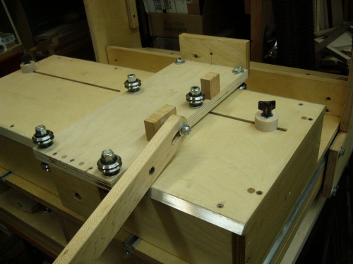
Great work by Georges Frerot. He used V-Groove Bearings, this improve coming soon in my design. Also he used a common USA Router. He wrote:
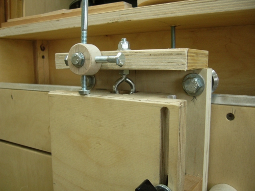
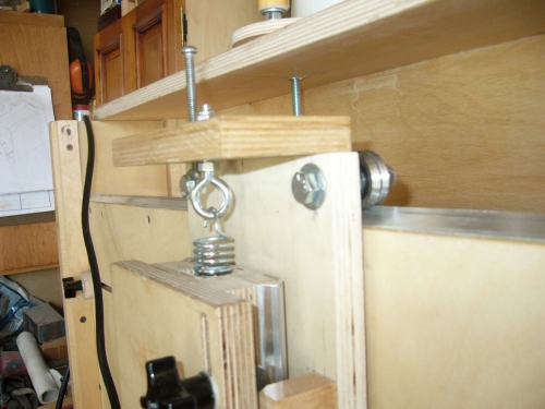
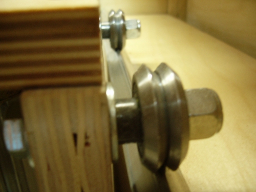
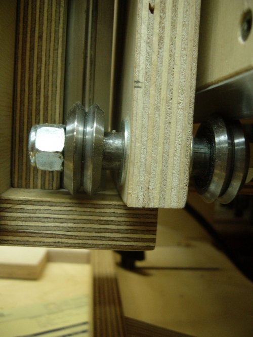
To install the bearings you can keep such parts which have been installed. It will take only clogged up the old holes to be adjusted with the gauge of new bearings. And check the "internal distance between the bearings, is what is most important. I calculated 3mm for the scope inside the bearing.
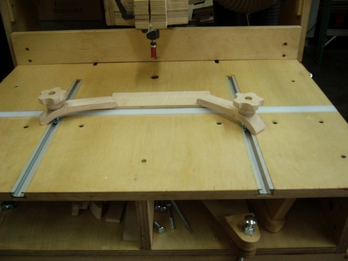
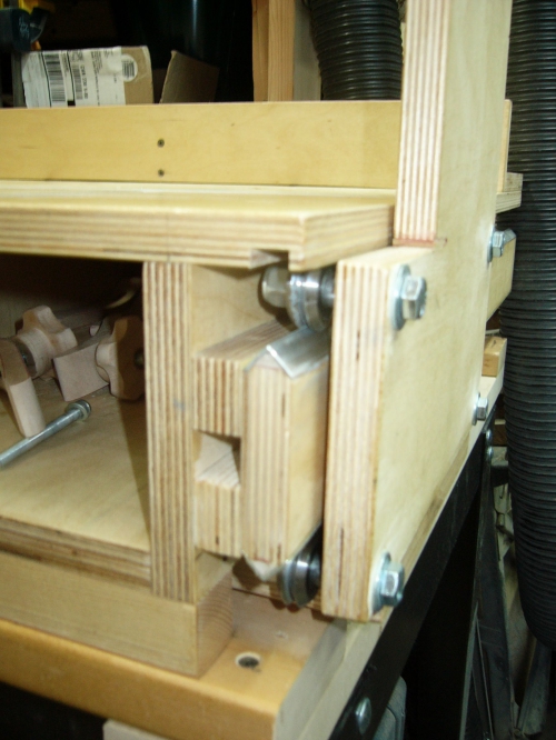
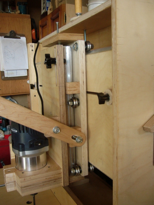
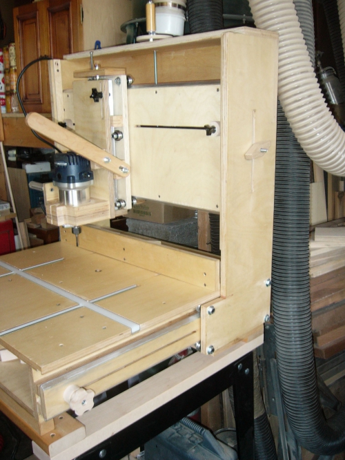
Then I installed a piece of pipe 3/8 in x 1/2 ex by d 1/4 "thickness, in order to havethe right distance. You absolutely have to take 3/8 bolts the metric does not in thisdimension. On picture No. 6 that warm-up in exhibit no. 6 in the plans, we see theslides on the side, my rating is 81 mm (3 3/16) with metal slide. I didn't redo the parts, so I was forced to make a Groove under the table of 12mm X 6 mm deep.
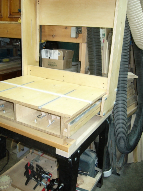
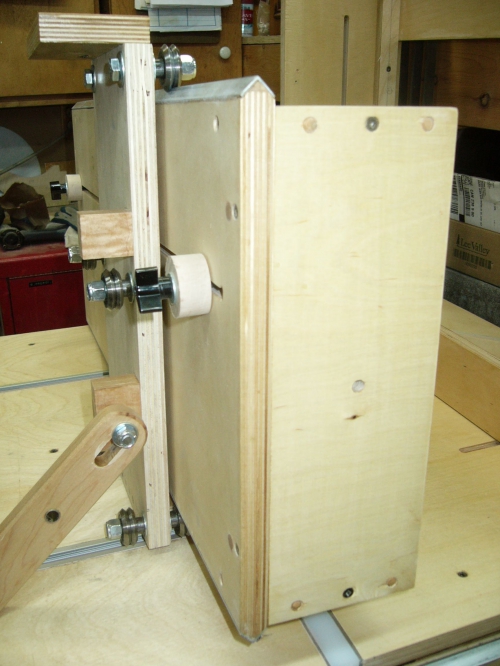
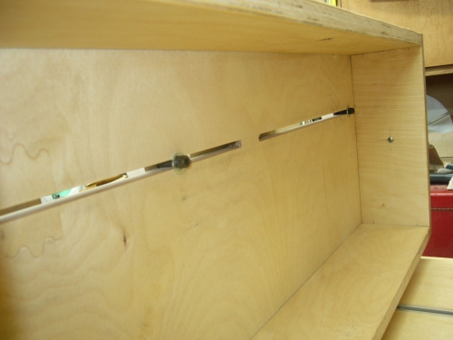
For ex. No. 19,(photo 19,19A) my dimensions are 324 mm (12 3/4) with steel slides. For room no. 25 (photo 25, 25A) support of routerLes dimensions are 107.5 mm(4 1/4) with steel slides. There are two tubes of 1/4 of each side as it should.
Other 3D Router Readers Project.
To install the bearings you can keep such parts which have been installed. It will take only clogged up the old holes to be adjusted with the gauge of new bearings. And check the "internal distance between the bearings, is what is most important. I calculated 3mm for the scope inside the bearing.
Then I installed a piece of pipe 3/8 in x 1/2 ex by d 1/4 "thickness, in order to havethe right distance. You absolutely have to take 3/8 bolts the metric does not in thisdimension. On picture No. 6 that warm-up in exhibit no. 6 in the plans, we see theslides on the side, my rating is 81 mm (3 3/16) with metal slide. I didn't redo the parts, so I was forced to make a Groove under the table of 12mm X 6 mm deep.
For ex. No. 19,(photo 19,19A) my dimensions are 324 mm (12 3/4) with steel slides. For room no. 25 (photo 25, 25A) support of routerLes dimensions are 107.5 mm(4 1/4) with steel slides. There are two tubes of 1/4 of each side as it should.
Other 3D Router Readers Project.